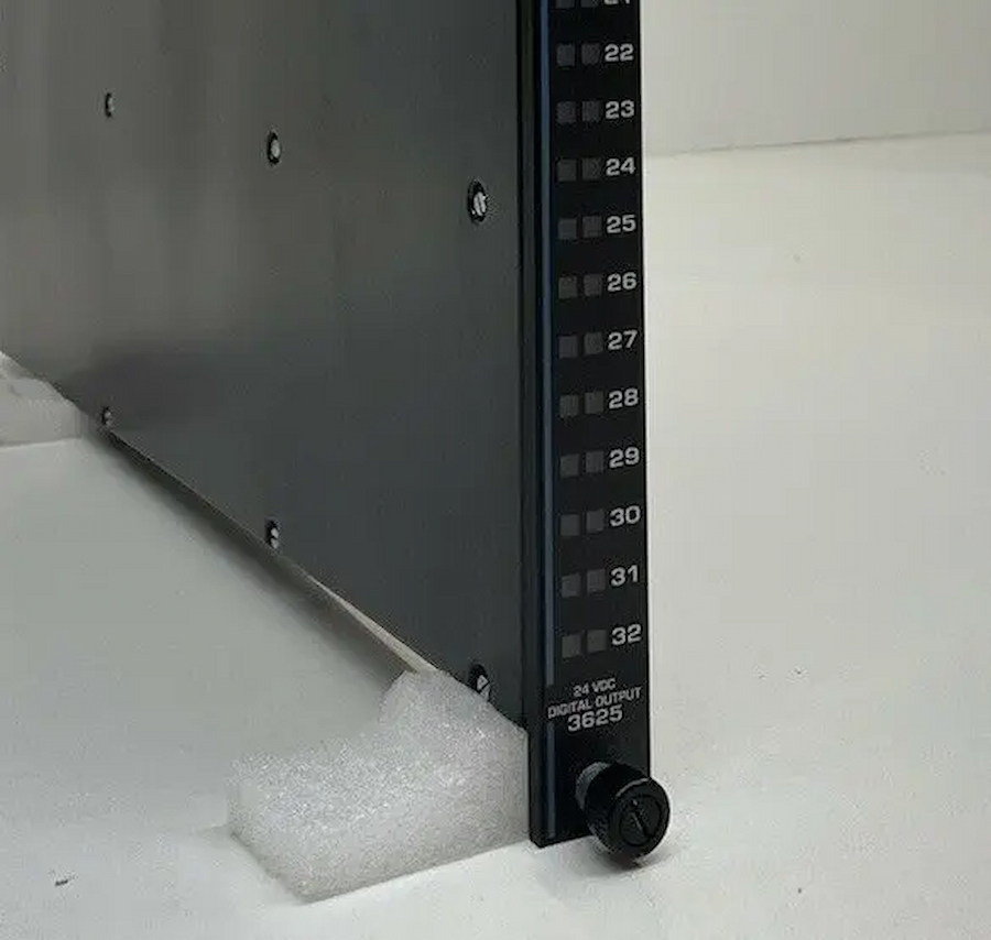
Invensys Triconex 3625
Each Digital Output Module houses the circuitry for three identical, isolated channels. Each channel includes an I/O microprocessor which receives its output table from the I/O communication processor on its corresponding Main Processor. All the Digital Output Modules, except the dual DC modules, use special quadruplicated output circuitry which votes on the individual output signals just before they are applied to the load. This voter circuitry is based on parallel-series paths which pass power if the drivers for Channels A and B, or Channels B and C, or Channels A and C command them to close—in other words, 2-out-of-3 drivers voted On. The dual Digital Output Modules provide a single parallel or series path, with the 2-out-of-3 voting process applied individually to each switch.
The quadruplicated output circuitry provides multiple redundancy for all critical signal paths, guaranteeing safety and maximum availability. The dual output module provides just enough redundancy to ensure safe operation. Dual modules are optimized for those safety-critical applications where low cost is more important than maximum availability.
Digital Output Modules include the hot-spare feature which allows online replacement of a faulty module. Like all I/O modules, Digital Output Modules require a separate field termination assembly with a cable interface to the Tricon controller backplane. Each module is mechanically keyed to prevent improper installation in a configured chassis.
Digital Output Modules are designed to source the current to field devices. Field power must be wired to each output point on a field termination module.

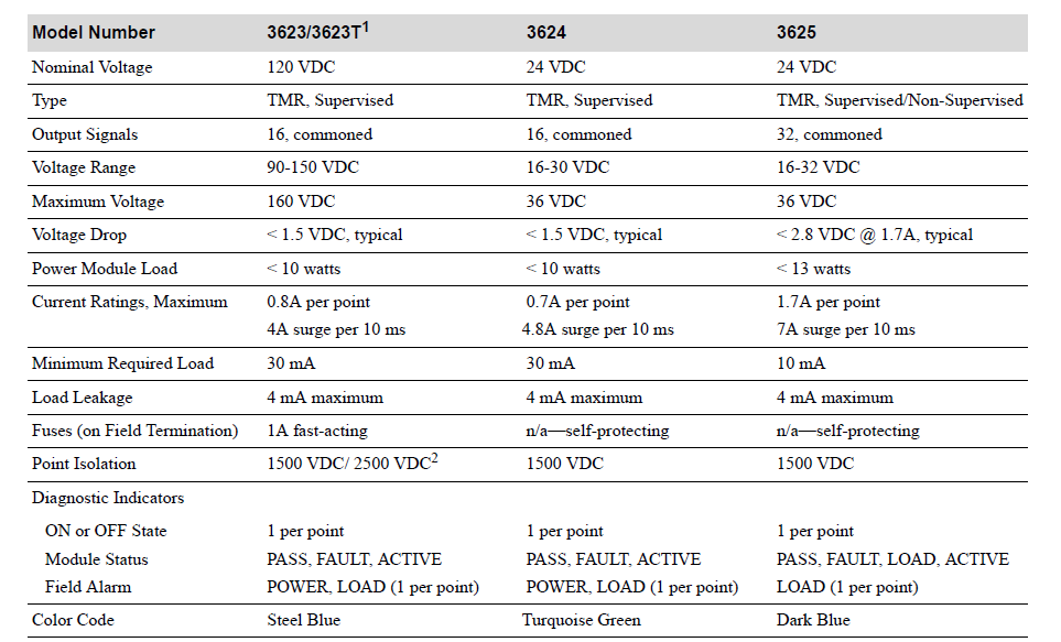
3625 Digital Output Specifications
| Feature |
Specification |
| Color code |
Dark blue |
| Number of output signals |
32, commoned |
| Recommended voltage range |
16–32 VDC |
| Nominal voltage |
24 VDC |
| Maximum voltage |
36 VDC |
| Logic power |
< 13 watts |
| Current ratings, maximum |
1.70 ± 10%amps/point, 5 amps surge/7 ms |
| Total module output current (all points) |
10 amps/termination panel |
| Minimum required load |
10 mA |
| Leakage current to load |
4 mA, maximum |
| Fuses (field termination module) |
Not required; output switches are self-protected against over-voltage, over-temperature, and overcurrent |
| Status indicator: On or Off state1 |
1 per point |
| Status indicator: Module status |
Pass, Fault, Load, Active |
| Status indicator: Field alarm1 |
Load (1 per point) |
| System-to-field isolation |
1500 VDC minimum |
| Point supervision |
Can be programmed per point |
| Short/Open circuit detection threshold |
Programmable per supervised point |
| Output diagnostic fault coverage2: Maximum output toggle rate |
Every 60 ms |
| Diagnostic glitch duration |
2 ms maximum, 200 μs typical |
|
On-state voltage drop:
At backplane
|
< 0.25 VDC typical @ 250mA
< 1.7 VDC @ 1.7A
|
|
On-state voltage drop:
With external termination, 10-foot cable
|
< 1.25 VDC typical @ 250mA
< 4.7 VDC @ 1.7A
|
|
On-state voltage drop:
With external termination, 99-foot cable
|
< 2.25 VDC typical @ 250mA
< 6.7 VDC @ 1.7A
|
| Inductive kick-back protection (reverse EMF) |
Output switches are self-protected |


100% brand new and original,All the goods will be tested before shipment.
For the in stock items, we will send the order out within 5-7 days after receive the payment.
Global supplier of quality automation and control components.
Topteng offers a 12-month warranty from the date of delivery.
In the event of non-conforming product ( if damaged or incorrect product is received ),
Any nonconformity must be reported within 7 days of receipt of goods.
Questions? Call +86 18050017653 or Email sales4@nseauto.com